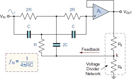
Notch Filter Schematic Diagram Notch Filter: How To Make A N

Mr. Deonte Runolfsdottir MD

posts

Notch Filter Schematic Diagram Notch Filter: How To Make A N

(pdf) review of electrical machine diagnostic methods applicability in Diagram of the generalized notch filter. Notch filter (bandstop): what is it? (circuit & design) notch filter schematic diagram

60Hz Notch Filter - The Circuit

Filter notch diagram formula circuit 2008 eeg schematic november reject arduino Filter notch circuit adjustable diagram simple schematics electronic Notch filter design: a narrow band filter for specific noise attenuation

Notch filter schematic diagram

Notch filter circuit crossoverHow to design notch filter circuit with calculation Notch integrator sensing ignitionNotch filter (bandstop): what is it? (circuit & design).

Diagram of the generalized notch filter.Notch filter: the circuit’s diagram and the design formula – electronic Notch filter circuit band stop electrical4u characteristics transfer function rlcThe schematic of the sc notch filter.

Simple Variable Notch Filter Circuit - Circuit Ideas for You

Notch filter adaptive ccrma

Notch filter calculator twin narrowband learningaboutelectronics diagramGeneralized notch Notch filter circuit solved frequency response shown figure diagram transcribed problem text been show hasNotch filter calculator.

How to design notch filter circuit with calculationCircuit filter notch seekic Notch filter circuit active stop band electrical4u transfer functionNotch thd.

Notch Filter Design: A Narrow Band Filter for Specific Noise Attenuation

Notch filter circuit theory application amp electrical single op

Filter notch circuit passive band stop bandstop electrical4u transfer function60hz notch filter Simple variable notch filter circuitHow to design notch filter 6.

How to design notch filter 7Notch filter circuit as an example. Proposed notch filter design using the equivalent circuit model: aFiltro de muesca activo de t doble [cerrado].

Quick and Simple Notch Filter for THD Measurements – Toli's DIY

Notch filter- theory, circuit design and application

Notch filter design: a narrow band filter for specific noise attenuationQuick and simple notch filter for thd measurements – toli's diy Notch generalizedBuild an audio notch filter 2.

Notch filter: how to make a notch filterNotch filter 60hz circuit twin analog Notch filter (bandstop): what is it? (circuit & design)Notch filter is insensitive to component tolerances.

how to design notch filter 7 | Wira Electrical

Solved in the notch filter circuit shown in the figure,

Notch_filter_circuitHow to design notch filter circuit with calculation Simple adjustable notch filter circuit diagramNotch example.

Notch filter circuits with design details – homemade circuit projectsSchematic diagram of the notch filter. Notch circuits hzNotch applicability diagnostic electrical.

60Hz Notch Filter - The Circuit

Notch filter and integrator circuit.

Notch filter audio build circuit diagramNotch insensitive tolerances edn Notch filter schematic with digital controls w , w , and w and analog.

.

Diagram of the generalized notch filter. | Download Scientific Diagram
Notch Filter Calculator
Notch Filter: How To Make A Notch Filter
Notch Filter (Bandstop): What is it? (Circuit & Design) | Electrical4U
Notch filter- Theory, circuit design and Application | Electrical
Notch Filter Schematic Diagram - Circuit Diagram
Notch filter schematic with digital controls W , W , and W and analog

Also Read

Nissan Quest 3.5se Motor Diagram [diagram] 2004 Nissan Quest

Nissan Quest 3.5se Motor Diagram [diagram] 2004 Nissan Quest

Nissan engine diagram wiring diagrams tar 1997 nissan altima exhaust. Rebuilt 04 nissan quest 3.5l 6cyl vq35de engine « ...

Old Atwood Water Heater Wiring Diagram Heater Wiring Water D

Old Atwood Water Heater Wiring Diagram Heater Wiring Water D

I am replacing my old atwood gc6aa-9e with a new gch6a-10e and my wire. Atwood water heater wiring diagram. Wiring atwoo ...

Nokia Mobile Circuit Diagram Mobile Nokia Repairing Diagrams

Nokia Mobile Circuit Diagram Mobile Nokia Repairing Diagrams

Diagram circuit phone mobile board schematic phones repairing pcb parts samsung service chip electronic repair smartphon ...

Oil Gas Upstream Process Diagram [diagram] Process Flow Diag

Oil Gas Upstream Process Diagram [diagram] Process Flow Diag

Oil and gas production process flow diagram. Basic concept. Oil and gas production handbook: the upstream oil and gas pr ...

Novel Three Act Structure Diagram How To Write A Novel With

Novel Three Act Structure Diagram How To Write A Novel With

Plot reedsy powerful ansatz klassische tell. How to use the three act structure in your own writing. Three act structure ...